How EMC simulation is helpful for IC application Reference board designs | Part 2 of 2
Dec 29 2022
By: ![]() Joe Sivaswamy, &
Joe Sivaswamy, &![]() Dr. Bibhu Prasad Nayak, Published on December 29, 2022
Dr. Bibhu Prasad Nayak, Published on December 29, 2022
This blog is a follow up to part 1 of EMC simulation for IC reference design boards. If you have not read the part 1 of this blog series, we encourage you to read it here.
In this article, we review how simulations help to validate an Isolated gate driver for compliance to CISPR25 radiated emissions using a reference design evaluation board.
Technical information for this article is referenced from IEEE publication 9947145
Background
Isolation is critical in high-voltage automotive and industrial applications to maintain functionality and protect against electric shocks. In applications of power rails of 800V or higher, for additional isolation, reinforced isolation devices are used. Reinforced isolation is the equivalent of two basic isolation layers enabled through a single isolation barrier.
One such application device is an isolated gate/switch driver which serves as a buffer circuit that amplifies a low-power input from a microcontroller and other similar sources to drive semiconductor power switches efficiently.
The EVM board referenced in this article is for a reinforced isolation gate driver implementation IC, enabled through a single laminate air-core transformer. Inductive coupling of the transformer provides power and control signaling transmission for the driver stage.
EMC issues with reinforced isolated gate drivers
Data transitions through the reinforced isolation transformer typically have sharp edge rates that potentially can cause conducted and radiated emissions due to the generation of high di/dt and dv/dt transient loops in the system (due to both package and PCB).
EMC simulation on the EVM board for radiated emission helps to identify two primary mechanisms as significant contributors to the emission noise. These include PCB edge and input-to-output dipole emissions. The main component of emissions is the common-mode current injected across the isolation barrier.
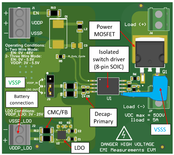
Isolated switch driver IC EVM board
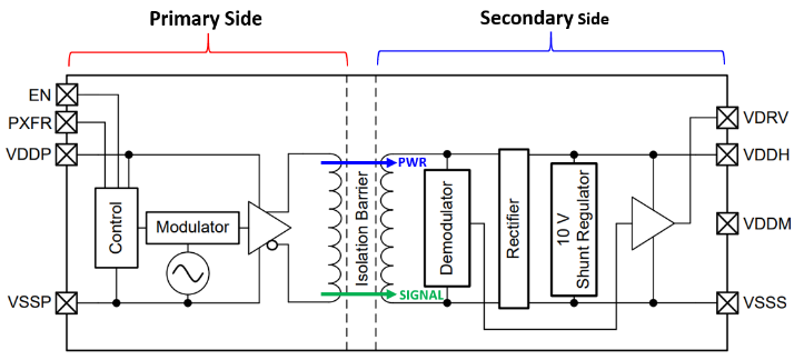
The device under test, an 8 pin SOIC pack, is a fully integrated reinforced isolated power switch driver. (Figure. 1). It features a 10-V gate drive with a 1.5/3-A peak source and sink current with a reinforced isolation rating of 5-kVRMS. The primary side includes a transmitter that drives an alternating current into the primary winding of an integrated transformer and uses spread-spectrum techniques for improving EMI performance. The transformer is designed on a laminate-based substrate.
The evaluation module for the device (EVM) is a 2-layer PCB designed and optimized for CISPR 25 EMC requirements.
Noise source model extraction for the simulation
With a system-level transient analysis, the voltage vs. time waveform between primary GND and secondary GND is extracted as the noise source stimuli/excitation for the simulation.
The field analysis is set up and performed using the simulation software. Figure 3 shows the setup in the EMC virtual modeling and simulation platform. The simulated emission profile is then compared to CISPR 25 radiated emission measurements envelope.

EMC Simulation vs Measurement Correlation
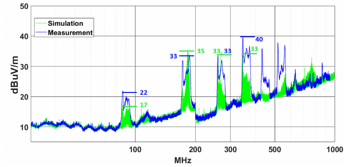
Figure. 4 shows the radiated emission simulation versus measurement results comparison. The results correlate well for frequency band 30-300MHz (within +/-3dB magnitude). Every resonant peak that corresponds to switcher fundamental and harmonic frequencies is recovered. For the 450MHz and 540MHz, over a 10dB difference was observed between simulation and measurement.
Key findings
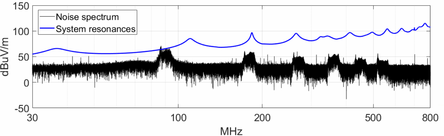
The main advantage of doing a system simulation is understanding the system behavior under the influence of the noise generated from the IC. In this case, simulation reveals that emission is high when the system resonance frequency matches with the peaks of the noise spectrum. This information can be useful when it comes to meeting the emission standard by judiciously choosing the noise spectrum.
Conclusions
EMC simulation with predictive modeling helps to optimize the design performance of a device using an EVM before testing the product for compliance.
References: CISPR 25 Radiated Emission Simulation and Measurement Correlation of an Automotive Reinforced Isolated Switch Driver. https://ieeexplore.ieee.org/document/9947145
To read more such informative blogs on EMC simulations, follow our LinkedIn Newsletter EMC Simulation trends