The Technology Behind EMI/EMC Simulation
Why EMI/EMC Is Hard to Simulate
Most EMI/EMC validation still happens after a prototype reaches the lab. Nearly 95% of engineering relies on physical measurements, making EMC one of the last stages of hardware verification. Two main challenges make simulation difficult.

Requires Accurate IC Behaviour
EMC failures often originate at the integrated circuit. In emissions tests the IC acts as the noise source, while in immunity tests it becomes the noise victim. Without accurate IC models, predicting pass/fail outcomes is extremely difficult.
Involves System-Scale Simulation
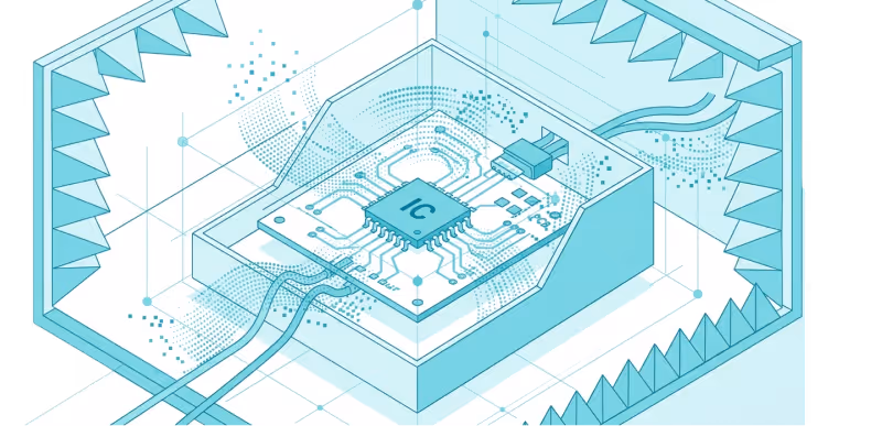
EMI/EMC simulations must capture interactions across an entire system- from ICs and PCB layouts to cables, enclosures, and lab test equipment. Traditional electromagnetic solvers struggle with this scale since they require large free-space meshes, accurate IC models, and enormous compute resources.
Bridging the EMC Modelling Gap
Predicting EMI/EMC is an inherently multi-scale challenge. Modern electronic design requires understanding interactions that span from nanometer-scale Power MOSFETs and micrometer-scale ICs, up to millimeter packages, centimeter PCBs, and ultimately meter-scale system harnesses.Traditional solvers struggle to bridge these domains efficiently.
SimYog addresses this by deploying a purpose-built hybrid technology architecture that combines highly optimized physics-based Electromagnetic Solvers with sophisticated data-based IC and system Models.
This allows hardware designers to perform predictive simulation workflows to achieve EMC compliance prior to physical prototyping.


A Solver Built for EMC
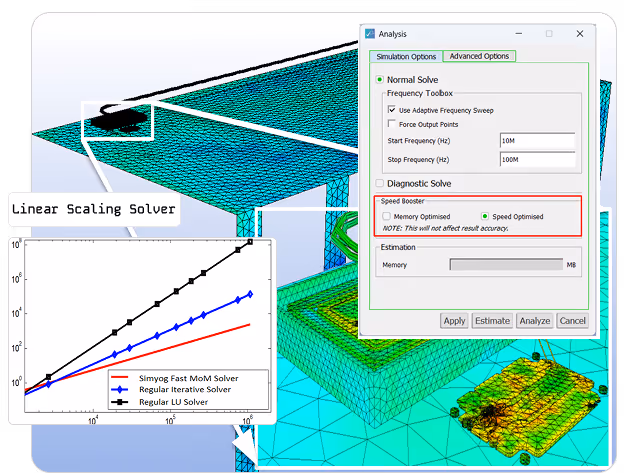
At the heart of SimYog is a 3D full-wave Method of Moments (MoM) solver designed specifically for EMC problems.
Unlike traditional solvers such as FEM that mesh entire volumes of empty space, MoM discretizes only structural surfaces; making it significantly more efficient for assemblies involving PCBs, cables, and antennas.
Linear-scaling matrix compression for large simulations
Hybrid parallel architecture for multi-core and multi-machine processing
Coupled circuit-electromagnetic modeling
Adaptive mesh refinement for accuracy
EMC-specific adaptive frequency sweep for faster simulations
Low frequency stability for scalable simulation
Modelling What Traditional Tools Cannot
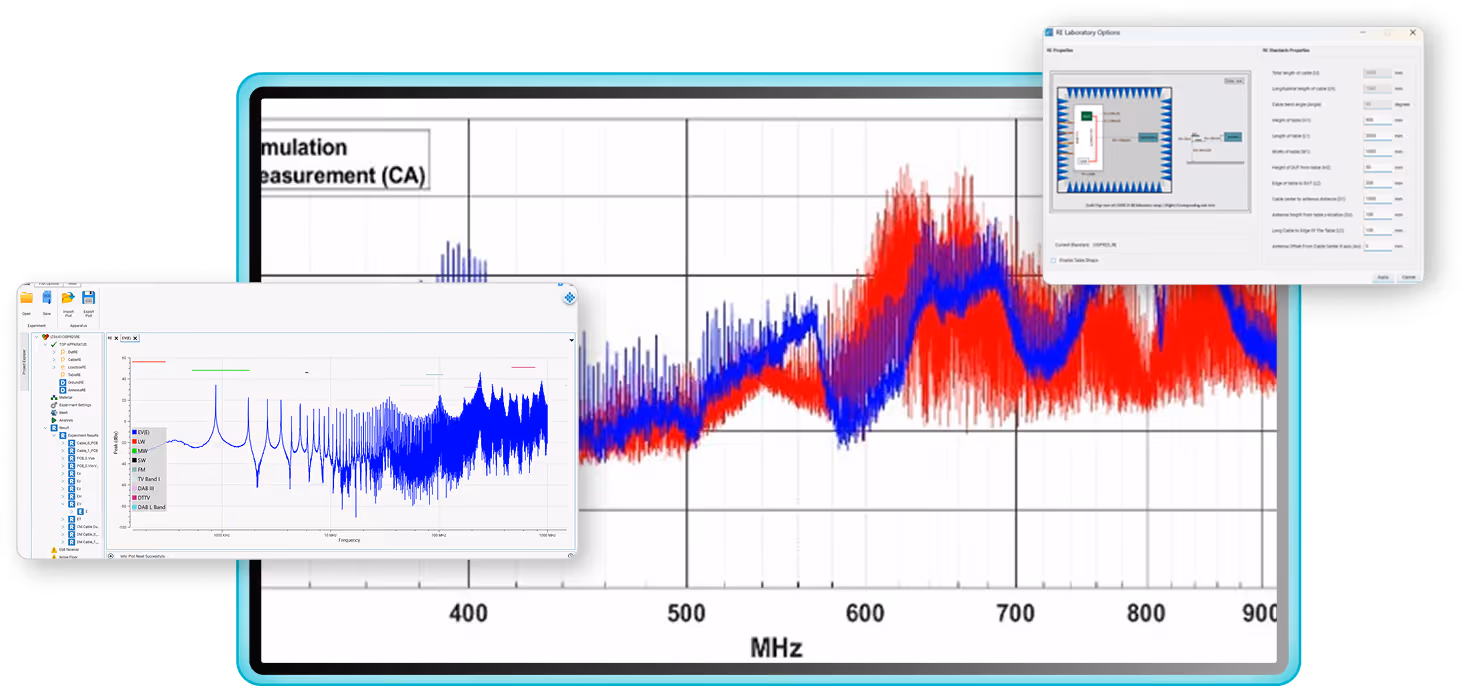
Pre-configured EMC Test Environments
Simulate standardized setups such as CISPR 25 and ISO 11452 without manually building laboratory models. This enables full test-environment simulation directly from design data.
Built-In Equipment Library
- Line Impedance Stabilization Networks (LISNs)
- Antennas and striplines
- EMI receivers
- Injection clamps for BCI testing
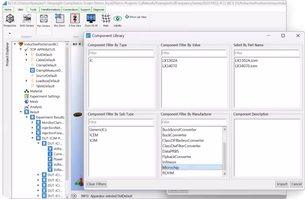
IC Emission Models (ICEM)
Automatically generate emission profiles using datasheet parameters or imported switching waveforms.
Machine-Learning IC Noise Models (Patented)
Neural-network surrogate models predict conducted noise across changing operating conditions.
IC Immunity Models (ICIM)
Translate Direct Power Injection (DPI) measurements into simulation models to predict failures in immunity tests.
System-Level Black-Box Models
Enable suppliers to share EMC behavior without exposing proprietary circuit designs.
Diagnose Failures Faster
When an EMC failure occurs, knowing that it failed is not enough. SimYog provides a suite of advanced diagnostic tools to isolate root causes and test mitigations instantly:
Current Segregation
Automatically separates Common-Mode (CM) and Differential-Mode (DM) currents and voltages at the LISN or cable, allowing engineers to determine the exact type of filtering required.
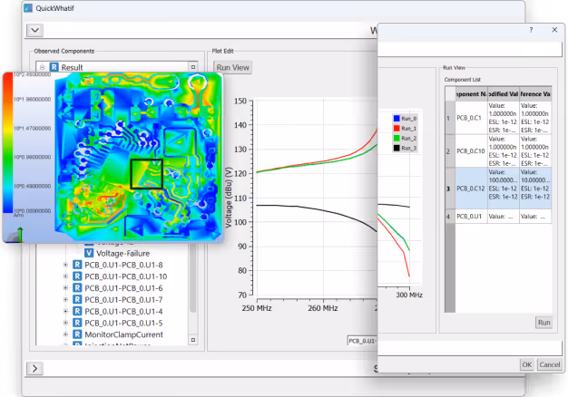
Sensitivity & Quick What-If Analysis
Generates granular sensitivity maps that quantify the relative impact of individual PCB components on induced voltages across a frequency sweep. Engineers can virtually swap component values and immediately see the impact on the emission/immunity profile without running a full re-simulation.
Spatial Visualization
Provides high-resolution current density maps and near E/H field plots to physically locate emission hotspots on the board, guiding immediate layout corrections.

AI Assisted EMC Engineering
SimYog includes SahAI, an integrated AI assistant designed to guide engineers through simulation workflows.
- Help configure EMC tests
- Assist with PCB imports
- Guide simulation setup
- Interpret diagnostic results
Ready to run your first simulation?
Get a technical walkthrough or schedule a demo with our engineering team