Simulation tool designed for EMC test engineer
Nov 26 2022
![]() by Joe Sivaswamy, Updated on November 26, 2022
by Joe Sivaswamy, Updated on November 26, 2022
Computational electromagnetic simulation tools have been in use for more than a decade. Yet, hardware design engineers have not been able to use them effectively.
Reasons for the limited use of simulation tools for EMC testing
In most cases, engineers involved in EMC compliance testing hesitate to use EMC simulation tools. This is due to a lack of EM solver knowledge. In general, EM Simulation engineers that work on signal and power-integrity analysis, employ simulation tools for EMC analysis. They generally don’t get involved in EMC compliance testing by themselves and are not familiar with EMC standards.
Traditional EM solvers are not designed specifically for EMC testing and do not generate test results that can be correlated to measurement results for EMC compliance.
An Ideal Simulation tool for EMC testing
An ideal EMC simulation software should be designed to be used as a virtual EMC test lab environment so that the user could go through the same process of getting products tested as in an EMC measurement lab. It should follow the same steps performed in EMC measurements, keeping the complexity of EM solver to run in the background of the simulation.
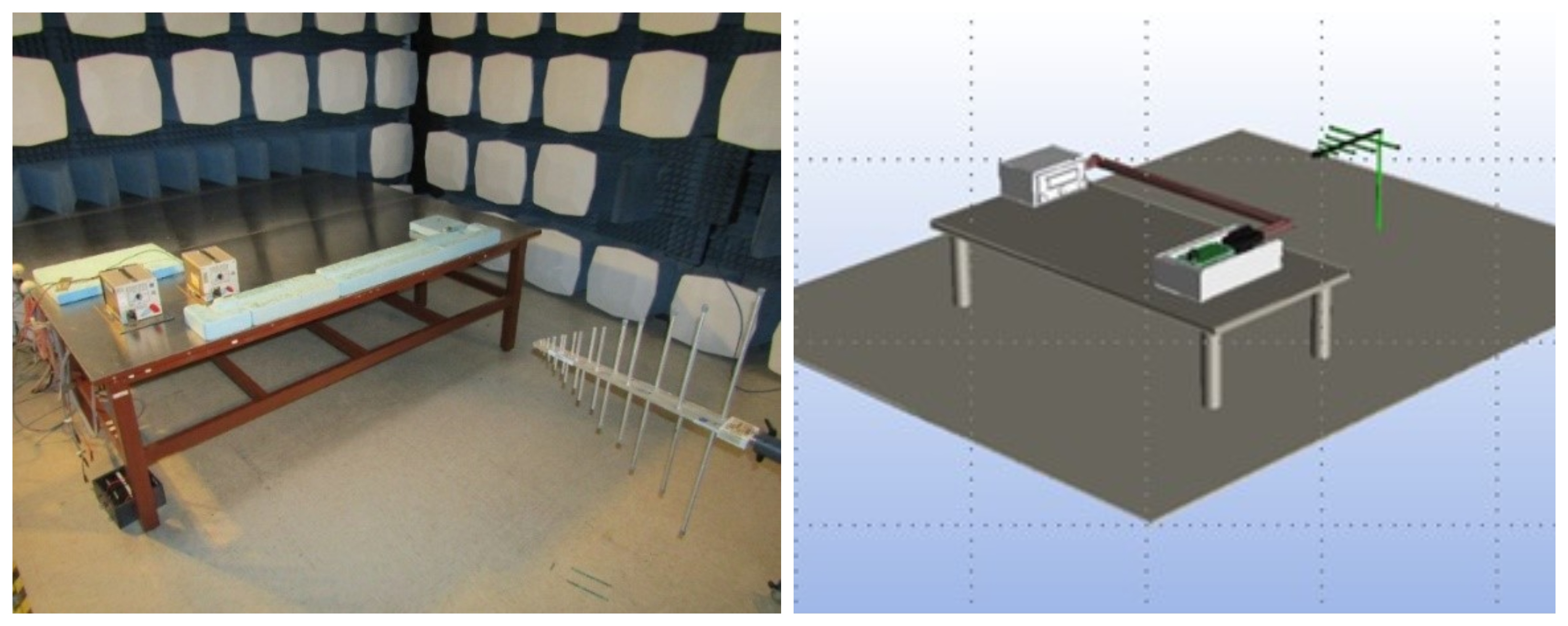 Figure 1: Measurement lab Vs a Simulation lab
A well-designed simulation software will enable the hardware engineers to make the best of both worlds. It will not only allow the engineer to understand the product’s EMC behavior by running simulations in a virtual lab. But will also help the engineer validate the product for EMC compliance in a measurement lab.
The simulation analysis and diagnostics help to understand the root cause of the problem to resolve the issues, in the process help in designing EMI resilient products instead of using mitigation methods to resolve EMC problems. Simulations help to understand the physics of the product under test, to characterize the device EMC behavior in running diagnostics to resolve problems. The investigations help to evaluate the coupling paths and analyze the emission sources independently to determine the magnitude and impedance at different points of the coupling path.

Figure 2: Comparing real word EMI to measurement setup and simulation results
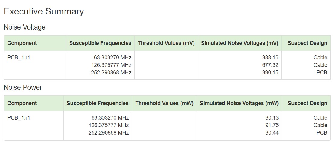 Figure 3: Diagnostics and analysis features of Simulation
EMI modeling and simulations have an inherent advantage. During the early stages of design, modeling and simulations can be done even in the absence of any real hardware. Thus, measurements can be carried out even in the absence of a physical product. These benefits make computational modeling a practical choice to determine the EMC behavior of a product when in the development phase.
System-level EMC simulation
In today’s world, using simulation, system-level product design can be done in parallel with the development of the sub-system components of the system. In the same way, system-level EMC simulations can be run in parallel to modeling the EMC behavior of sub-system components, leading to a better understanding on the EMC behavior of the entire system when sub-system components of the system get characterized for their EMC behavior.
Note: The figures and feature examples given above are referenced from Simyog Technology’s simulation software ‘Compliance Scope’. Additional information on the software is available at www.simyog.com