Authored by: Harikiran Muniganti, Co-Founder
There are three practical MoM approaches for dielectrics:
Surface Integral Equations (PMCHWT):
Use equivalent electric and magnetic surface currents on dielectric interfaces. Best suited for piecewise-constant (homogeneous) dielectrics; requires only surface meshes.Volume Integral Equations (VIE) with SWG basis:
Discretize the dielectric volume using Schaubert–Wilton–Glisson (SWG) (divergence-conforming) elements to model electric and magnetic polarization currents. Applicable to inhomogeneous, graded, anisotropic, or lossy dielectrics.Spectral-Domain MoM with multilayer Green’s functions:
Treat the PCB stack-up as a planar stratified medium and use multilayer Green’s functions (Sommerfeld integrals) so only the conductor geometries are meshed. Ideal for boards and substrates with known dielectric layering. This is a 2.5D approximation and may be insufficient for arbitrary 3D shapes.
Compliance-Scope 4.10.0 achieves accuracy with improved speed using hybrid triangle-tetrahedral-prism meshing:
For systems containing both conductors and dielectrics, a Volume–Surface Integral Equation (VSIE) hybrid is used: RWG basis functions on conductor triangles and divergence-conforming bases (e.g., SWG) on dielectric tetrahedra. In layered structures such as PCBs, using prisms aligned with the stack-up typically yields fewer unknowns than all-tetrahedral meshes at the same accuracy because the through-thickness variation is resolved with 1–2 prismatic layers instead of many tetrahedral layers.
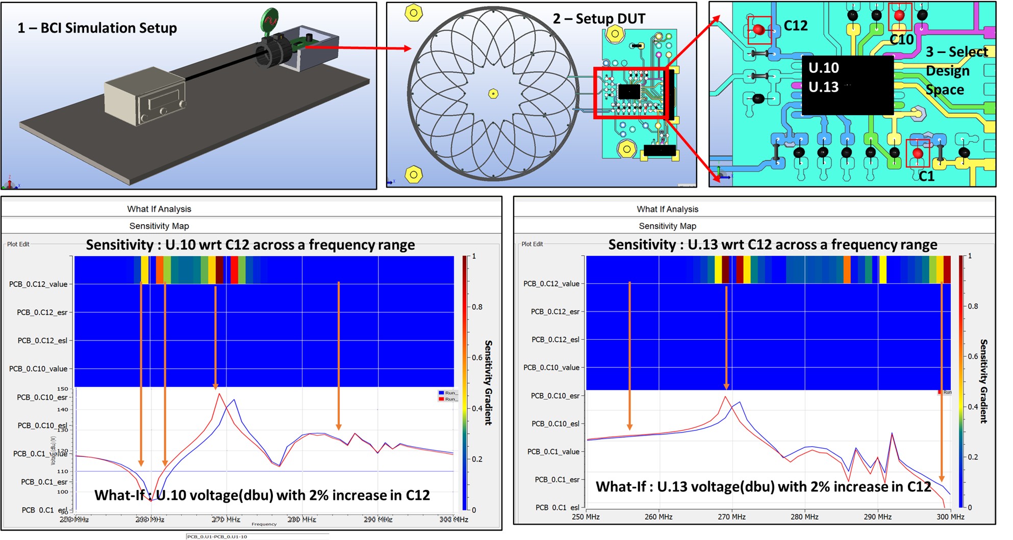
Figure 1(a) shows the DUT view of the test setup and Figure 1(b) compares the vertical E-field EV for the CISPR 25 radiated-emissions setup with the PCB dielectric (i) meshed with prisms, (ii) meshed with tetrahedra, and (iii) omitted (conductor-only). The prism and tetrahedra results are virtually indistinguishable indicating that a prismatic discretization captures the dielectric physics with fidelity comparable to a tetrahedral mesh while requiring fewer elements. In contrast, the conductor-only curve departs noticeably, with shifts in resonance frequencies and changes in peak levels, reflecting the missing substrate permittivity and loss paths. The cable is modelled with a tetrahedral mesh in all three cases, so the observed discrepancies arise from the PCB dielectric treatment rather than the cable discretization.
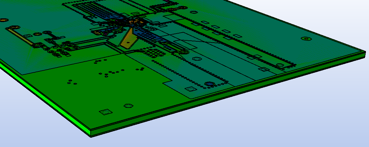 Figure 1(a): CISPR 25 RE Test setup
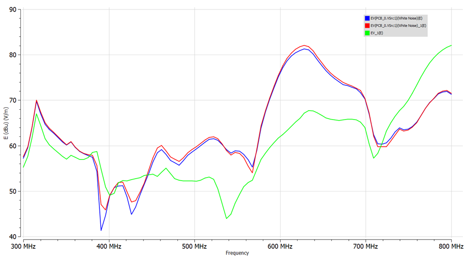
Figure 1(b): CISPR 25 radiated emissions- vertical E-field Ev(f) for PCB dielectric meshed using prisms (blue), meshed using tetrahedra (red), and omitted / conductor-only (green)
Figure 2 summarizes the resulting performance gains across representative cases. Speedup is defined as S=TTet/TPrism (higher is better) and is measured as end-to-end solver wall-clock time under identical solver settings and matched accuracy.
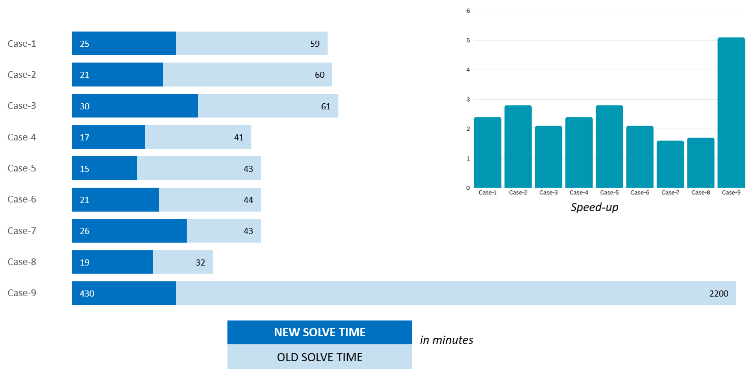
Figure 2: Runtime speedup of prism-meshed layered dielectrics relative to a tetrahedral baseline across the cases
© 2025 SimYog Technologies Pvt. Ltd. – All Rights Reserved.